

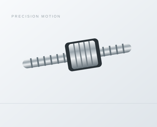
PFU4020 Rolled Ball Screw
Series / Model PFU4020
Review PFU4020 rolled ball screw dimensions: 38 mm shaft, 20 mm lead and 90 mm nut length. Compare mounting details and request engineering confirmation.
Overview
PFU4020 is a PFU reference in the catalog’s Stock Rolled Ball Screw section. Its row lists d = 38 mm, a 20 mm lead and L = 90 mm. Use this page to review the model’s geometry and prepare a configuration inquiry.
Review the changed 40-series interface
The source gives d = 38 mm, D = 64 mm, A = 100 mm and H = 83 mm for PFU4020. These dimensions differ from PFU4010, even though both names begin with 40. The 20 mm lead and three-circuit row need their own load, speed and mounting review.
PFU4020 catalog dimensions and ratings
| Parameter | Reference | Unit |
|---|---|---|
| Shaft d | 38 | mm |
| Lead I | 20 | mm/rev |
| Ball diameter Da | 6 | mm |
| Circuits n | 3 | count |
| Basic dynamic rating Ca | 29330 | N |
| Basic static rating Coa | 56390 | N |
| Nut body D | 64 | mm |
| Flange A | 100 | mm |
| B | 14 | mm |
| Nut length L | 90 | mm |
| W | 81 | mm |
| H | 83 | mm |
| Hole diameter X | 9 | mm |
Dimensions retain the source symbols and printed precision. I denotes lead, Da ball diameter and n the source number of circuits. Ca and Coa are basic dynamic and static ratings in newtons. Do not treat either rating as an allowable payload or a complete life calculation.
Compare PFU4020 with PFU4010
| Field | PFU4020 | PFU4010 |
|---|---|---|
| d | 38 | 39.5 |
| I | 20 | 10 |
| D | 64 | 63 |
| L | 90 | 93 |
| A | 100 | 93 |
The comparison uses separately verified catalog rows. Matching dimensions support an initial envelope review only. Different leads change travel per screw revolution, while the required rotational speed still depends on the target linear speed. Neither the table nor the model name establishes accuracy grade, preload or supplied configuration.
Installation and inquiry checklist
For the PFU flange, review A = 100 mm, W = 81 mm, H = 83 mm and X = 9 mm together. Confirm the applicable hole arrangement, angular orientation and bolt access against the controlled drawing. The family illustration is not a model-specific manufacturing drawing.
- Identify PFU4020, rolled process, quantity, working stroke and overall screw length. Attach the screw-end and nut-housing drawings.
- Provide axial force through the complete cycle, travel speed, acceleration, mounting orientation and required life. Review buckling and critical speed for the actual unsupported span.
- State positioning requirements, acceptable axial play, lubrication access and environmental protection. Confirm offered preload, accuracy and inspection conditions with engineering.
Allow for support bearings, end clearances and maintenance access beyond the listed nut length. Confirm the offered assembly and drawing revision before committing the machine layout.
Questions about PFU4020
Does PFU4020 specify the complete screw length?
No. The catalog lists L = 90 mm for the nut. Working stroke, screw length, end machining and support locations must be specified separately.
Can PFU4020 replace PFU4010 without a drawing check?
No. The comparison preserves each row’s d, lead, D, L and A values. Confirm the full mounting interface, shaft ends, load cycle and motion requirements; the catalog does not establish interchangeability.
What does the PFU4020 load table establish?
The source lists Ca = 29330 N and Coa = 56390 N as basic ratings. They are not permissible machine loads. Confirm the rating basis, duty cycle, life target and safety checks before selection.
Source and engineering confirmation
See the original ball screw catalog, PDF page 4 (printed page 3); the PFU header and drawing are on PDF page 3. These are catalog reference values. Engineering must confirm the exact offered dimensions, configuration and controlled drawing. The historical section title does not establish current stock, price or delivery.
Send the model and duty details through the PFU4020 configuration inquiry.
Need help selecting a model or configuration?
Catalog reference only. Confirm the offered assembly, controlled drawing, duty cycle and commercial terms.