
Ball Spline Thermal Movement: Define the Axial Datum and Freedom
November 5, 2026 · 6 min read
A ball spline allows relative axial movement between its shaft and nut while transmitting torque. That sliding freedom does not establish where an installed shaft is located axially or whether the complete mechanism can accommodate thermal movement. An external bearing, drive connection or tool attachment can restrain the same shaft elsewhere.
Review the thermal displacement path before treating a spline as an expansion provision. The question is which parts can move relative to which references as the machine changes temperature.
Separate nut retention from shaft axial location
The spline nut must remain correctly retained in its housing. Its axial retention concerns the nut body relative to that housing. The shaft’s axial location concerns a different pair of components: the shaft relative to the machine or its moving structure. Securing the nut body does not make the sliding shaft axially located through the spline contact.
Conversely, permitting shaft-to-nut sliding does not release a shaft trapped between external axial restraints. For example, two shaft attachments can define an axial distance independently of the spline nut between them. The thermal review must include those attachments. Keep the specified nut retention intact; an unapproved loose mounting is not a thermal accommodation method.
Choose the axial datum deliberately
Mark the interface that establishes the shaft’s intended axial reference. Then identify the surface or working point whose position matters to the process. These locations need not coincide. Expansion between the reference and the working point can change their separation even when the reference itself remains correctly located.
A locating/non-locating bearing arrangement illustrates the distinction: one support establishes axial location, while the other accommodates relative axial displacement. That is a bearing design principle, not a prescribed support arrangement for every ball spline. The selected bearings, seats and retention must actually provide the assigned functions.
Do not label an end simply “floating.” State which components move relative to each other, in which direction, and over what permitted range. A support may restrain radial movement while allowing axial movement through a specifically designed interface.
Trace the complete thermal displacement path
Follow the shaft from its axial datum through every bearing, coupling, drive connection, spline nut and attached tool. At each interface, distinguish required operating travel from movement intended to accommodate temperature changes. A coupling’s ability to transmit torque alone does not establish its allowable axial movement or axial reaction.
| Interface | Question to resolve |
|---|---|
| Nut to housing | What retains the nut body without relying on unintended movement? |
| Shaft to external support | Which support locates the shaft, and where is relative expansion accommodated? |
| Drive or tool connection | Does it preserve the intended freedom or introduce another axial restraint? |
If two connections restrain a changing separation, the result can include axial reaction and elastic deformation rather than unrestricted movement. Quantifying that response requires the actual temperatures, materials and stiffnesses. Removing a restraint can also change the machine’s functional load path, so review the complete arrangement before changing it.
Define temperature states and differential movement
Record the assembly and inspection temperature state, the expected operating states and any relevant cooling or shutdown state. Identify temperatures at the shaft, housing and locating structure separately. Their temperature changes and expansion may differ; one ambient reading cannot establish their relative displacement.
For a calculation, obtain verified material properties, reference lengths and temperature distributions for the actual components. State whether the model assumes uniform temperatures or includes gradients. A free-expansion estimate alone does not predict restraint force, housing distortion or installed working-point error.
Check the remaining movement at each operating position
Superimpose the assessed thermal displacement on the commanded motion when checking relative positions. Review the remaining accommodation at both ends of the permitted movement, including engagement boundaries and the travel limits of external connections. Check intermediate positions when the constraint arrangement changes during the cycle.
The shaft layout guide covers working-zone geometry. This thermal review adds the change in relative position between defined temperature states; it does not authorize extra travel beyond an approved assembly boundary.
Release the thermal assumptions with the drawing
Attach the axial datum, interface responsibilities, temperature states, predicted relative movements and acceptance requirements to one drawing revision. Define where position will be measured and under which temperature and motion conditions it must comply. Keep unresolved movement limits and material data visible for confirmation.
Download the thermal datum review worksheet (CSV). Include the proposed SL or SO reference and the external support drawings when requesting an assembly review.
Related products
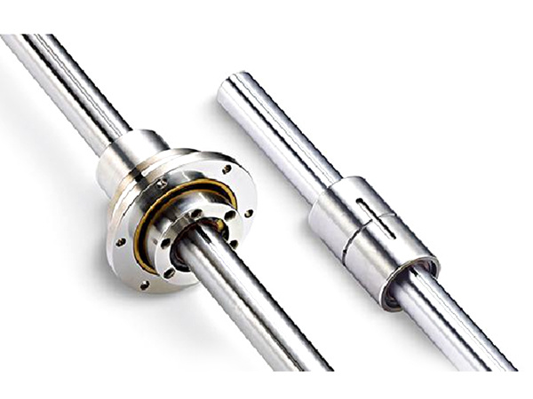
SL SERIES
Ball Spline is a precision mechanical transmission element suitable for applications requiring high precision, high rigidity, high speed and large loads, especially for round-trip and rotary movements.
View productSO SERIES
Ball Spline is a precision mechanical transmission element suitable for applications requiring high precision, high rigidity, high speed and large loads, especially for round-trip and rotary movements.
View product