

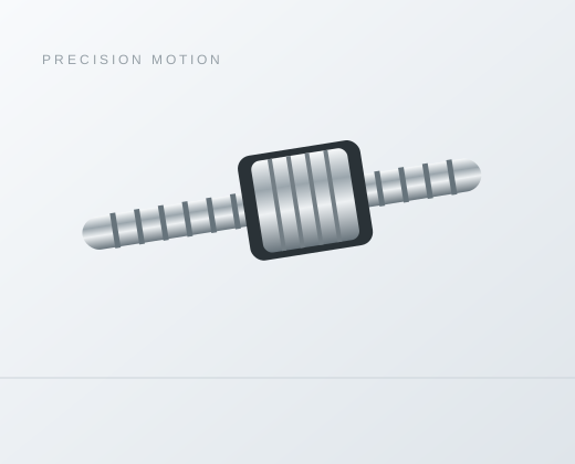
PCG2005 Rolled Ball Screw
Series / Model PCG2005
Review PCG2005 rolled ball screw dimensions: d 19 mm, 5 mm lead and M35x1.5 nut mounting thread. Request the exact drawing and configuration.
Overview
PCG2005 is a PCG threaded-nut reference from the rolled section of the Series Motion ball screw catalog. The row lists d = 19 mm and I = 5 mm per revolution. Use the dimensions below to prepare a drawing and configuration review.
A shared mounting thread needs a complete row check
The M35x1.5 mounting thread, 38 mm body diameter and B = 15 mm match the listed PCG2004 interface. PCG2005 uses a 5 mm lead, 3 mm balls and a 45 mm nut length. Keep those values with its own basic ratings rather than combining the lead of one row with the load data of another.
PCG2005 dimensions and basic ratings
| Parameter | Reference | Unit |
|---|---|---|
| Shaft callout d | 19 | mm |
| Lead I | 5 | mm/rev |
| Ball diameter Da | 3 | mm |
| Number of circuits n | 3 | count |
| Basic dynamic rating Ca | 8520 | N |
| Basic static rating Coa | 14220 | N |
| Nut body D | 38 | mm |
| Nut length L | 45 | mm |
| Drawing callout B | 15 | mm |
| Nut mounting thread A | M35x1.5 | metric thread |
Values retain the printed precision and source symbols. The catalog heading identifies this as a rolled row; the PCG prefix alone is not a manufacturing-process designation. The table is reference data, not a released manufacturing drawing or confirmation of current stock.
Compare the mounting envelope with PCG2004
| Field | PCG2005 | PCG2004 |
|---|---|---|
| d | 19 | 19.5 |
| I | 5 | 4 |
| D | 38 | 38 |
| L | 45 | 43 |
| B | 15 | 15 |
| A | M35x1.5 | M35x1.5 |
Use the complete selected row. Similar external dimensions do not establish interchangeability, equivalent load capacity, preload or positioning accuracy. Confirm the mating housing and actual shaft-end geometry before replacement or design release.
Information for configuration review
- Specify PCG2005, rolled process, quantity, required stroke and overall screw length. Include the nut-housing and shaft-end drawings.
- Provide the axial load through the complete cycle, speed, acceleration, mounting direction and required service life. Identify the support arrangement and unsupported length.
- State positioning requirements, permitted axial play, lubrication access and environmental conditions. Ask for the offered accuracy, preload and inspection conditions to be identified in the quotation.
Confirm the supplied configuration, drawing revision, availability and delivery before committing the assembly layout. A catalog basic rating does not replace an application-specific selection calculation.
Questions about PCG2005
What does M35x1.5 mean for PCG2005?
It is the nut mounting-thread designation A. The screw lead is I = 5 mm per revolution. Confirm the mating thread, engagement and retention on the controlled assembly drawing.
Is the 45 mm length the working stroke?
No. L = 45 mm is the catalog nut length. Working stroke, overall screw length, end machining and support positions must be specified separately.
Do the PCG2005 ratings establish the permitted machine load?
No. Ca = 8520 N and Coa = 14220 N are the catalog basic dynamic and static ratings. Selection also requires the load cycle, rating basis, required life, support arrangement and separate static, buckling and speed checks.
Review the source and request a drawing
Check the original PCG catalog row with the drawing and field definitions on PDF page 5. See the 20 mm size table for other catalog configurations. Send a PCG2005 rolled configuration inquiry with the application details and drawing requirements.