

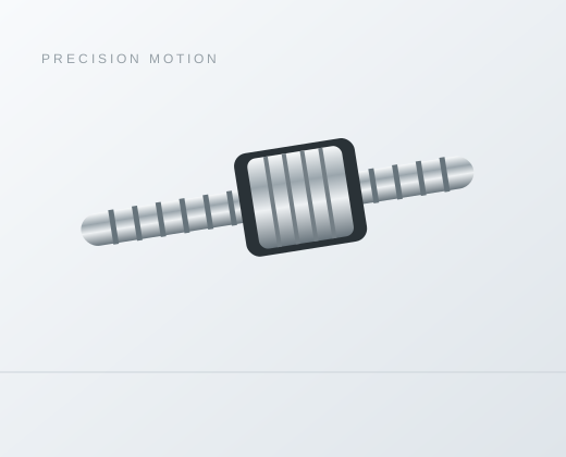
PFI1605 Ball Screw
Series / Model PFI1605
Review PFI1605 ball screw dimensions: d = 15 mm, 5 mm lead and L = 50 mm. Compare the nut interface and request a drawing review.
Overview
PFI1605 is a PFI ball-screw catalog reference with d = 15 mm and I = 5 mm lead. This page supports a model-specific drawing and quotation review, with published dimensions and a comparison to PFI1604.
Allow 50 mm nut length for the 15 mm shaft, 5 mm lead option
The flange callouts A = 49 mm and W = 39 mm match PFI1604, but the shaft value and nut length differ. Check the axial space behind the flange before reusing the carriage layout.
d = 15 mm versus 15.3 for PFI1604; I = 5 mm versus 4 for PFI1604; L = 50 mm versus 45 for PFI1604; Ca(N) = 9170 N versus 7190 for PFI1604. These are catalog comparisons, not an interchangeability approval. Check the entire assembly whenever the screw or nut model changes.
PFI1605 dimensions and basic load ratings
| Drawing field | Value | Unit or notation |
|---|---|---|
| d | 15 | mm |
| I | 5 | mm |
| Da | 3 | mm |
| n | 4 | catalog circuit notation |
| Ca(N) | 9170 | N |
| Coa(N) | 13720 | N |
| D | 30 | mm |
| A | 49 | mm |
| B | 10 | mm |
| L | 50 | mm |
| W | 39 | mm |
I denotes lead, Da denotes ball diameter and n is the catalog circuit notation. Keep n exactly as shown; it is not a thread-start count. Ca and Coa are basic dynamic and static load ratings in newtons. They are not a continuous operating-load limit or a promised service life.
Review the nut-to-carriage interface
The PFI drawing is a flanged-nut arrangement. Review D = 30 mm, flange callout A = 49 mm, B = 10 mm, L = 50 mm and W = 39 mm together. The table does not supply every bolt, counterbore, lubrication and mating-fit requirement. Select the correct flange view and confirm a controlled mounting drawing.
The listed L dimension is the nut length, not the working stroke. Specify shaft length, end machining, bearing supports and end clearances separately. Mark the nut orientation and lubrication access in the assembly so that the mounting decision can be checked before ordering.
Confirm the duty before selecting the assembly
Use the 5 mm lead when translating the required linear travel into screw rotation. Lead alone does not establish achievable speed or positioning accuracy. Check screw length, support arrangement, rotational speed, acceleration, axial loading and required service life together.
Provide the external guide arrangement and any side loads or moments on the carriage. Review lubrication, seals and contamination protection for the actual installation. Confirm the raceway manufacturing method, accuracy and preload or clearance of the offered configuration; the catalog heading and model reference are not a stock, delivery or performance commitment.
Questions about PFI1605
How does PFI1605 differ from PFI1604?
d = 15 mm versus 15.3 for PFI1604; I = 5 mm versus 4 for PFI1604; L = 50 mm versus 45 for PFI1604; Ca(N) = 9170 N versus 7190 for PFI1604. The flange callouts A = 49 mm and W = 39 mm match PFI1604, but the shaft value and nut length differ. Check the axial space behind the flange before reusing the carriage layout.
Can the PFI1605 flange be drilled from these table values alone?
No. A = 49 mm and W = 39 mm are reference callouts, not a complete manufacturing drawing. Confirm the offered flange view, hole pattern, fasteners and mating fits before drilling the bracket.
Does PFI1605 guarantee a particular accuracy or preload?
The model identifies a catalog configuration. Confirm the complete designation, raceway manufacturing method, accuracy class, axial clearance or preload and inspection conditions in the quotation. A model prefix alone does not establish these properties.
What should I send for a PFI1605 quotation?
Specify PFI1605, quantity, working stroke, total shaft length, end-machining drawing, mounting arrangement, axial load cycle, travel speed, acceleration, required life and accuracy. Include lubrication access and the operating environment, and request confirmation of the offered drawing revision.
Request the PFI1605 drawing and configuration
Review the complete ball-screw family tables and drawings for the original notation. Send your layout and duty information through the PFI1605 inquiry page. Ask the quotation to identify the exact assembly, shaft ends, drawing revision and inspection requirements.
Need help selecting a model or configuration?
This page is a catalog reference. Send the exact model, drawing and load cycle to confirm the offered configuration and commercial terms.