

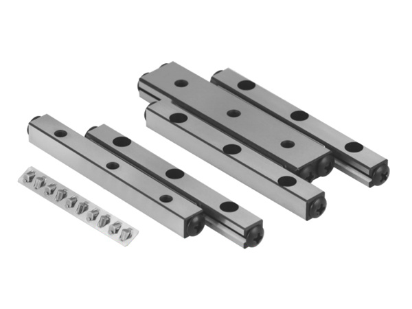
VR SERIES
Series / Model VR
Crossed roller guide is a high precision, high load, high rigidity linear motion track, usually used in robots, automation equipment, machining centers, precision measurement equipment and other equipment and systems that need to achieve high precision linear motion.
Overview
Application industry
Crossed roller guide is a high precision, high load, high rigidity linear motion track, usually used in robots, automation equipment, machining centers, precision measurement equipment and other equipment and systems that need to achieve high precision linear motion.
Model Description
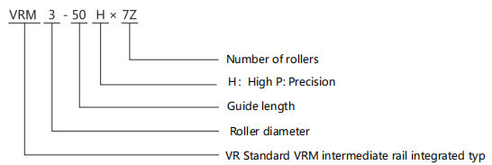
1 set of VR series refers to the state in which 4 rails and 2 cages are combined together
1 set of VRM series refers to a state in which 2 rails, 1 intermediate rail and 2 cages are combined together
● When only dedicated guide are selected ●When only the roller cage is selected

Precautions
● Guide length
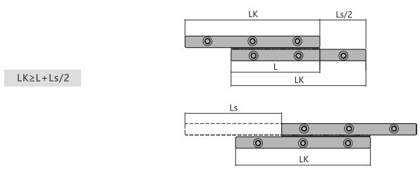
The movement of the roller cage is 1/2 of the movement of the table and moves in the same direction as the table movement. Let the length of the cage be L and the stroke length be Ls, so in order to prevent the cage from being cantilevered from the track table, the length of the track LK should be
● Cage deviation
Although the cage can operate extremely correctly, the cage sometimes deviates due to torque, vertical use, uneven contact, mechanical vibration, etc.
● About the stop
In order to prevent the cage from falling off, although the stopper is installed on the end face of the rail, due to overtravel, etc., the stopper frequently collides with the stopper, causing wear of the stopper and loosening of the stopper fixing screw, etc., and the stopper may fall off. s reason. Therefore, it is recommended to set an external stop, which not only prevents overtravel, but also prevents conflict with the cage
Installation
(1) Fix the guide rails 1, 2 and 3, and temporarily fix the guide rail 4
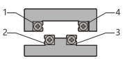
(2) Remove the blocking screw on one side of the guide rail, carefully insert the roller cage, replace the blocking screw, move the slide left and right, and adjust the cage to the center of the rail
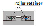
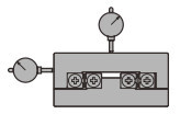
(3) Fix the measuring scale on the center and side of the slide table
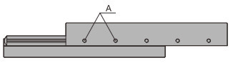
(4) Move the slide table to the end of one side, and then gently lock the preload adjustment screw A
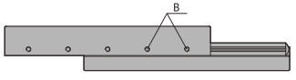
(5) Move the slide table to the end of the other side, and then gently lock the preload adjustment screw B
(6)Return the sliding table to the center position, lock the clearance adjustment screw C of the sliding table, and adjust the clearance of the sliding table to zero
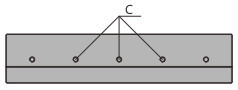
(7)Then fix the guide rail 4 for sure
Screw installation
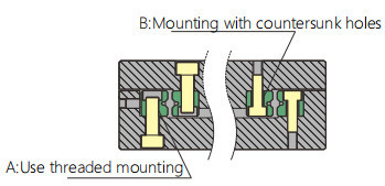
| VR1 | VR2 | VR3 | VR4 | VR6 | VR9 | |
| Mounting with countersunk holes |
M1.4 | M2 | M3 | M4 | M5 | M6 |
| Use threaded mounting | M2 | M3 | M4 | M5 | M6 | M8 |
※No matter which installation method is used, the countersunk surface cannot be used as the installation surface.
Cross roller guide: V1 series
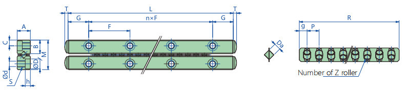
mm
| Maximum Lead | Major dimensions | ||||||||||||
| combination dimension | Installation dimention | ||||||||||||
| M | A | L | n×F | G | B | C | S | d | D | h | T | ||
| VR1-20×5z | 12 | 8.5 | 4 | 20 | 1×10 | 5 | 3.9 | 1.8 | M2 | 1.65 | 3 | 1.4 | 0.8 |
| VR1-30×7z | 22 | 8.5 | 4 | 30 | 2×10 | 5 | 3.9 | 1.8 | M2 | 1.65 | 3 | 1.4 | 0.8 |
| VR1-40×10z | 27 | 8.5 | 4 | 40 | 3×10 | 5 | 3.9 | 1.8 | M2 | 1.65 | 3 | 1.4 | 0.8 |
| VR1-50×13z | 32 | 8.5 | 4 | 5o | 4×10 | 5 | 3.9 | 1.8 | M2 | 1.65 | 3 | 1.4 | 0.8 |
| VR1-60×16z | 37 | 8.5 | 4 | 60 | 5×10 | 5 | 3.9 | 1.8 | M2 | 1.65 | 3 | 1.4 | 0.8 |
| VR1-70×19z | 42 | 8.5 | 4 | 70 | 6×10 | 5 | 3.9 | 1.8 | M2 | 1.65 | 3 | 1.4 | 0.8 |
| vR1-80×21z | 52 | 8.5 | 4 | 80 | 7×10 | 5 | 3.9 | 1.8 | M2 | 1.65 | 3 | 1.4 | 0.8 |
| Retainer dimension | Basic load rating(Each roller) | ||||||
| Da | R | g | p | z | C(kN) | co(kN) | |
| VR1-20×5z | 1.5 | 14 | 2.0 | s | 0.098 | 0.069 | |
| VR1-30×7z | 1.5 | 19 | 2.0 | 7 | 0.098 | 0.069 | |
| VR1-40×10z | 1.5 | 26.5 | 2.0 | 10 | 0.098 | 0.069 | |
| VR1-50×13z | 1.5 | 34 | 2.0 | 13 | 0.098 | 0.069 | |
| vR1-60×16z | 1.5 | 41.5 | 2.0 | 16 | 0.098 | 0.069 | |
| VR1-70×19z | 1.5 | 49 | 2.0 | 19 | 0.098 | 0.069 | |
| R1-80×21z | 1.5 | 54 | 2.0 | 21 | 0.098 | 0.069 | |
C:Basic dynamic load rating (KN) C0:Basic static load rating (KN)
| Guide | Roller | Retainer | |
| Material | Gcr15 | Gcr15 | sus304 |
| Hardness | HRC58~ | HRC60~ |
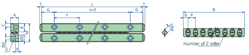
mm
| Maximum Lead | Major dimensions | ||||||||||||
| Combination dimension | lnstallation dimention | ||||||||||||
| M | A | L | n×F | G | B | C | S | d | D | h | T | ||
| VR3-50×7z | 28 | 18 | 8 | 5o | 1×25 | 12.5 | 8.3 | 3.5 | M4 | 3.4 | 6 | 3.1 | 2 |
| VR3-75×10z | 48 | 18 | 8 | 75 | 2×25 | 12.5 | 8.3 | 3.5 | M4 | 3.4 | 6 | 3.1 | 2 |
| VR3-100×14z | 58 | 18 | 8 | 100 | 3×25 | 12.5 | 8.3 | 3.5 | M4 | 3.4 | 6 | 3.1 | 2 |
| VR3-125×17z | 78 | 18 | 8 | 125 | 4×25 | 12.5 | 8.3 | 3.5 | M4 | 3.4 | 6 | 3.1 | 2 |
| VR3-150×21Z | 88 | 18 | 8 | 150 | 5×25 | 12.5 | 8.3 | 3.5 | M4 | 3.4 | 6 | 3.1 | 2 |
| VR3-175×24Z | 108 | 18 | 8 | 175 | 6×25 | 12.5 | 8.3 | 3.5 | M4 | 3.4 | 6 | 3.1 | 2 |
| VR3-200×28z | 118 | 18 | 8 | 200 | 7×25 | 12.5 | 8.3 | 3.5 | M4 | 3.4 | 6 | 3.1 | 2 |
| VR3-225x31z | 138 | 18 | 8 | 225 | 8×25 | 12.5 | 8.3 | 3.5 | M4 | 3.4 | 6 | 3.1 | 2 |
| Retainer dimension | Basic load rating(Each roller) | ||||||
| Da | R | g | p | z | C(kN) | co(kN) | |
| VR3-50×7z | 3 | 36 | 3 | 5 | 7 | 0.363 | 0.275 |
| VR3-75×10Z | 3 | 51 | 3 | 5 | 10 | 0.363 | 0.275 |
| vR3-100×14z | 3 | 71 | 3 | 5 | 14 | 0.363 | 0.275 |
| vR3-125×17z | 3 | 86 | 3 | 5 | 17 | 0.363 | 0.275 |
| VR3-150×21z | 3 | 106 | 3 | 5 | 21 | 0.363 | 0.275 |
| VR3-175×24z | 3 | 121 | 3 | 5 | 24 | 0.363 | 0.275 |
| VR3-200×28z | 3 | 141 | 3 | 5 | 28 | 0.363 | 0.275 |
| VR3-225×31z | 3 | 156 | 3 | 5 | 31 | 0.363 | 0.275 |
C:Basic dynamic load rating (KN) C0:Basic static load rating (KN)
| Guide | Roller | Retainer | |
| Material | Gcr15 | Gcr15 | sus304 |
| Hardness | HRC58~ | HRC60~ |
Cross roller guide V2 Series
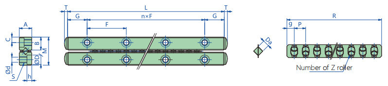
mm
| Maximum Lead | Major dimensions | ||||||||||||
| Combination dimensior | lnstallation dimention | ||||||||||||
| M | A | L | n×F | G | B | C | S | d | D | h | T | ||
| VR2-30×5z | 18 | 12 | 6 | 30 | 1×15 | 7.5 | 5.5 | 2.5 | M3 | 2.5 | 4.5 | 2 | 1.5 |
| VR2-45×8z | 24 | 12 | 6 | 45 | 2×15 | 7.5 | 5.5 | 2.5 | M3 | 2.5 | 4.5 | 2 | 1.5 |
| VR2-60×11z | 30 | 12 | 6 | 60 | 3×15 | 7.5 | 5.5 | 2.5 | M3 | 2.5 | 4.5 | 2 | 1.5 |
| VR2-75×13z | 44 | 12 | 6 | 75 | 4×15 | 7.5 | 5.5 | 2.5 | M3 | 2.5 | 4.5 | 2 | 1.5 |
| VR2-90×16z | 50 | 12 | 6 | 90 | 5×15 | 7.5 | 5.5 | 2.5 | M3 | 2.5 | 4.5 | 2 | 1.5 |
| VR2-105×18z | 64 | 12 | 6 | 105 | 6×15 | 7.5 | 5.5 | 2.5 | M3 | 2.5 | 4.5 | 2 | 1.5 |
| VR2-120×21z | 70 | 12 | 6 | 120 | 7×15 | 7.5 | 5.5 | 2.5 | M3 | 2.5 | 4.5 | 2 | 1.5 |
| VR2-135×23z | 84 | 12 | 6 | 135 | 8×15 | 7.5 | 5.5 | 2.5 | M3 | 2.5 | 4.5 | 2 | 1.5 |
| Retainer dimension | Basic load rating(Each roller) | ||||||
| Da | R | g | p | z | C(kN) | co(kN) | |
| vR2-30×5z | 2 | 21 | 2.5 | 4 | s | 0.176 | 0.127 |
| vR2-45×8z | 2 | 33 | 2.5 | 8 | 0.176 | 0.127 | |
| VR2-60×11z | 2 | 45 | 2.5 | 11 | 0.176 | 0.127 | |
| VR2-75×13z | 2 | 53 | 2.5 | 13 | 0.176 | 0.127 | |
| VR2-90×16z | 2 | 65 | 2.5 | 16 | 0.176 | 0.127 | |
| VR2-105×18z | 2 | 73 | 2.5 | 18 | 0.176 | 0.127 | |
| VR2-120×21z | 2 | 85 | 2.5 | 21 | 0.176 | 0.127 | |
| VR2-135×23z | 2 | 93 | 2.5 | 23 | 0.176 | 0.127 | |
C:Basic dynamic load rating (KN) C0:Basic static load rating (KN)
| Guide | Roller | Retainer | |
| Material | Gcr15 | Gcr15 | sus304 |
| Hardness | HRC58~ | HRC60~ |
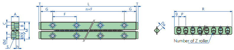
mm
| Maximum Lead | Major dimensions | ||||||||||||
| Combination dimension | Installation dimention | ||||||||||||
| M | A | L | n×F | G | B | C | S | d | D | h | T | ||
| VR4-80×7z | 58 | 22 | 11 | 80 | 1×40 | 20 | 10.2 | 4.5 | M5 | 4.3 | 8 | 4.2 | 2 |
| VR4-120×11z | 82 | 22 | 11 | 120 | 2×40 | 20 | 10.2 | 4.5 | M5 | 4.3 | 8 | 4.2 | 2 |
| VR4-160×15z | 106 | 22 | 11 | 160 | 3×40 | 20 | 10.2 | 4.5 | M5 | 4.3 | 8 | 4.2 | 2 |
| VR4-200×19z | 130 | 22 | 11 | 200 | 4×40 | 20 | 10.2 | 4.5 | M5 | 4.3 | 8 | 4.2 | 2 |
| vR4-240×23z | 154 | 22 | 11 | 240 | 5×40 | 20 | 10.2 | 4.5 | M5 | 4.3 | 8 | 4.2 | 2 |
| VR4-280×27z | 178 | 22 | 11 | 280 | 6×40 | 20 | 10.2 | 4.5 | M5 | 4.3 | 8 | 4.2 | 2 |
| VR4-320×31z | 202 | 22 | 11 | 320 | 7×40 | 20 | 10.2 | 4.5 | M5 | 4.3 | 8 | 4.2 | 2 |
| Retainer dimension | Basic load rating(Each roller) | ||||||
| Da | R | g | p | z | C(kN) | co(kN) | |
| VR4-80x7z | 4 | 51 | 4.5 | 7 | 7 | 0.764 | 0.637 |
| VR4-120×11z | 4 | 79 | 4.5 | 11 | 0.764 | 0.637 | |
| VR4-160×15z | 4 | 107 | 4.5 | 15 | 0.764 | 0.637 | |
| VR4-200×19z | 4 | 135 | 4.5 | 19 | 0.764 | 0.637 | |
| VR4-240×23Z | 4 | 163 | 4.5 | 23 | 0.764 | 0.637 | |
| VR4-280×27z | 4 | 191 | 4.5 | 27 | 0.764 | 0.637 | |
| vR4-320×31z | 4 | 219 | 4.5 | 31 | 0.764 | 0.637 | |
C:Basic dynamic load rating (KN) C0:Basic static load rating (KN)
| Guide | Roller | Retainer | |
| Material | Gcr15 | Gcr15 | sus304 |
| Hardness | HRC58~ | HRC60~ |
Cross roller guide: VR6 Series
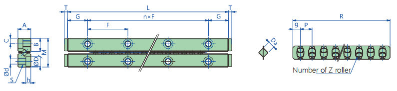
mm
| Maximum Lead | Major dimensions | ||||||||||||
| Combination dimension | lnstallation dimention | ||||||||||||
| M | A | L | n×F | G | B | C | S | d | D | h | T | ||
| VR6-100×7z | 44 | 30 | 15 | 100 | 1×50 | 25 | 14 | 6 | M6 | 5.2 | 9.5 | 5.2 | 3 |
| VR6-150×8z | 96 | 30 | 15 | 15o | 2×50 | 25 | 14 | 6 | M6 | 5.2 | 9.5 | 5.2 | 3 |
| vR6-200×11z | 148 | 30 | 15 | 200 | 3×50 | 25 | 14 | 6 | M6 | 5.2 | 9.5 | 5.2 | 3 |
| VR6-250×14z | 176 | 30 | 15 | 250 | 4×50 | 25 | 14 | 6 | M6 | 5.2 | 9.5 | 5.2 | 3 |
| VR6-300×17z | 204 | 30 | 15 | 300 | 5×50 | 25 | 14 | 6 | M6 | 5.2 | 9.5 | 5.2 | 3 |
| VR6-350×20z | 232 | 30 | 15 | 350 | 6×50 | 25 | 14 | 6 | M6 | 5.2 | 9.5 | 5.2 | 3 |
| Retainer dimension | Basic load rating(Each roller) | ||||||
| Da | R | g | p | z | C(kN) | co(kN) | |
| VR6-100×7z | 6 | 87 | 7.5 | 12 | 7 | 2.292 | 2.112 |
| vR6-150×8z | 6 | 99 | 7.5 | 12 | 8 | 2.292 | 2.112 |
| VR6-200×11z | 6 | 135 | 7.5 | 12 | 11 | 2.292 | 2.112 |
| VR6-250×14z | 6 | 171 | 7.5 | 12 | 14 | 2.292 | 2.112 |
| vR6-300×17z | 6 | 207 | 7.5 | 12 | 17 | 2.292 | 2.112 |
| VR6-350×20z | 6 | 243 | 7.5 | 12 | 20 | 2.292 | 2.112 |
C:Basic dynamic load rating (KN) C0:Basic static load rating (KN)
| Guide | Roller | Retainer | |
| Material | Gcr15 | Gcr15 | sus304 |
| Hardness | HRC58~ | HRC60~ |
Cross roller guide VR9 Series
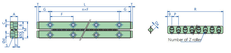
mm
| Maximum Lead | Major dimensions | ||||||||||||
| combination dimension | lnstallation dimention | ||||||||||||
| M | A | L | n×F | G | B | C | S | d | D | h | T | ||
| vR9-200×10z | 118 | 40 | 20 | 200 | 1 ×100 | 50 | 19.2 | 8 | M8 | 6.8 | 10.5 | 6.2 | 4 |
| VR9-300×15z | 178 | 40 | 20 | 300 | 2×100 | 50 | 19.2 | 8 | M8 | 6.8 | 10.5 | 6.2 | 4 |
| VR9-400×20z | 238 | 40 | 20 | 400 | 3×100 | 50 | 19.2 | 8 | M8 | 6.8 | 10.5 | 6.2 | 4 |
| VR9-500×25z | 298 | 40 | 20 | 500 | 4×100 | 50 | 19.2 | 8 | M8 | 6.8 | 10.5 | 6.2 | 4 |
| vR9-600×30z | 358 | 40 | 20 | 600 | 5×100 | 50 | 19.2 | 8 | M8 | 6.8 | 10.5 | 6.2 | 4 |
| Retainer dimension | Basic load rating(Each roller) | ||||||
| Da | R | g | p | z | C(kN) | co(kN) | |
| vR9-200×10z | 9 | 141 | 7.5 | 14 | 10 | 4.31 | 4.36 |
| VR9-300×15z | 9 | 211 | 7.5 | 14 | 15 | 4.31 | 4.36 |
| vR9-400×20z | 9 | 281 | 7.5 | 14 | 20 | 4.31 | 4.36 |
| VR9-500×25z | 9 | 351 | 7.5 | 14 | 25 | 4.31 | 4.36 |
| VR9-600×30z | 9 | 421 | 7.5 | 14 | 30 | 4.31 | 4.36 |
C:Basic dynamic load rating (KN) C0:Basic static load rating (KN)
| Guide | Roller | Retainer | |
| Material | Gcr15 | Gcr15 | sus304 |
| Hardness | HRC58~ | HRC60~ |
Application industry
Crossed roller guide is a high precision, high load, high rigidity linear motion track, usually used in robots, automation equipment, machining centers, precision measurement equipment and other equipment and systems that need to achieve high precision linear motion.
Cross Roller Guide
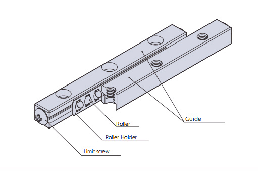
Product structure
In the VR type, the roller cage in which the precision rollers are orthogonally combined with each other is used in combination with the V-groove raceway provided on the dedicated track.By assembling two rows of roller guide rails in parallel, the rail system can withstand loads in four directions. In addition, since a preload can be applied to the cross-roller guide, a carriage mechanism with no clearance, high rigidity, and smooth movement can be obtained. Cross-roller guides are widely used in office equipment and peripheral equipment, various measuring instruments, precision equipment such as printed circuit board drilling machines, and slide parts of optical testers, optical tables, manipulation mechanisms, and X-ray devices.
Product features
●Long service life and high rigidity
Using the unique roller holding method, the effective contact length of the rollers has been increased by 1.7 times compared with the previous product, and the pitch interval of the rollers has been shortened, the number of rollers has been increased, and the rigidity has been increased by 2 times, which can obtain 6 times. lifespan. Therefore, it is possible to adequately design safety considerations for vibration and shock problems that are likely to occur in linear motion parts.
●Smooth movement
In the VR type, the roller cages are separated. Since the roller pockets in the cage are in contact with the roller surfaces, there is good lubricating oil retention, so there is no wear and friction, and smooth rolling motion can be obtained
Product accuracy
The accuracy of the rail dedicated to the Cross Roller Guide is divided into high grade (H) and precision grade (P) as shown in the table below
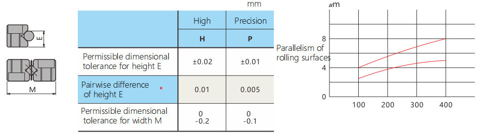
※Pairwise mutual difference of height E for 4 tracks used on the same plane
Need help selecting a model or configuration?
Send load, speed, stroke, environment and interface requirements for model confirmation.