Electric Cylinder Sizing: Record Load and Motion Throughout the Cycle
October 21, 2026 · 4 min read

Series Motion · Engineering and procurement guide
Before selecting an electric cylinder, divide one operating cycle into stages. For each stage, record the required force, start and end positions, speed, acceleration and duration.
A requirement such as “200 mm stroke, 1,500 N force” does not say whether the peak force acts briefly, throughout travel or during a stationary hold. Describe those conditions so the mechanism, motor and thermal demands can be assessed together. This worksheet does not replace a manufacturer’s sizing calculation.
Write one row for each phase
| Phase | Motion and time | Load and condition to record |
|---|---|---|
| Advance | Start/end position, move time, speed and acceleration | Moving mass, process force direction and guide resistance |
| Process or hold | Position, dwell time and whether position or force is controlled | Peak force, sustained force and acceptable movement under load |
| Return | Return distance, time and acceleration | Load direction, any attached tooling and changed process forces |
| Wait | Time until the next cycle | Whether the motor remains energized or the axis must hold a load |
Use a sign convention for direction. Separate the process force from the moving mass, and identify horizontal, inclined or vertical installation. For a vertical axis, describe the required response to loss of power; do not assume the screw mechanism will hold the load by itself. Guidance must account for side loading and moments rather than relying on the actuator rod to correct misalignment. [1]
A timing example, not a rated operating point
Consider a hypothetical cycle: advance 200 mm in 2 s, hold for 2 s, return 200 mm in 2 s, then wait for 4 s. The complete cycle is 10 s, giving 6 cycles/min, or 360 cycles/hour if repeated without interruption. The average travel speed during each move is 100 mm/s; peak speed will be higher if acceleration and deceleration occur within those same two seconds.
The actuator moves for 4 s of the 10 s cycle, or 40% of the cycle. During the separate 2 s hold, it remains stationary under load. Holding may still require motor current and produce heat, so the 40% figure alone cannot show whether the actuator can repeat this cycle without overheating. The load history, holding current, ambient temperature and the manufacturer’s definition of duty must also be checked. Include production pauses and the expected operating hours, and specify the period covered by those hours.
Check the complete package
Ask for review of peak and sustained force at the required speed, the compression and support conditions, and the available motor torque across the motion profile. A catalog peak thrust is not permission to apply that force continuously. Include ambient conditions, contamination and lubrication access. [1, 2]
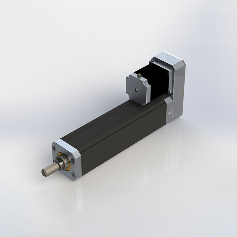
Usable stroke is not the retracted or extended overall length. Leave space for the body, rod attachment, motor arrangement, connectors and installation access. Identify the load guidance and the mounting geometry. Confirm the actual dimensions on the proposed configuration drawing rather than scaling a product photograph. [2]
Send the profile with the inquiry
- Completed phase table, cycle count and normal operating schedule.
- Moving mass, axial process-force profile and any offset load or external guidance.
- Mounting orientation, usable stroke and available installed envelope.
- Required positioning, repeatability, dwell behavior and power-loss response.
- Existing motor, drive and machine interface details, with their scope clearly identified.
Use the Electric Cylinder product page to start the discussion, then send the completed duty profile. Custom travel or interface requirements can be reviewed; the numerical example above is not a Series Motion performance claim or a limit on the dimensions that can be discussed. For a comparison of proposed supply packages, use the RFQ scope sheet.
Technical references
- Tolomatic — specifying electric rod actuators, Part 1 — Application loading, duty, force/velocity and side loading.
- Tolomatic — specifying electric rod actuators, Part 2 — Peak thrust, operating environment and complete package envelope.
Guide prepared from the technical references above and the linked Series Motion product information. Examples are illustrative; final dimensions, configuration and acceptance requirements must be agreed for the application.