

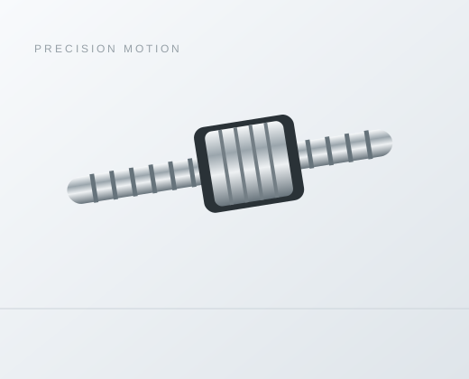
PFU0610 Rolled Miniature Ball Screw
Series / Model PFU0610
Check PFU0610 rolled ball screw data: 6 mm shaft diameter, 10 mm lead and 23 mm nut length. Review the motion and mounting changes, then send your drawing.
Overview
PFU0610 is a rolled reference with a 6 mm nominal shaft diameter and 10 mm lead. The catalog gives a 14 mm body D, 23 mm nut length L and basic ratings Ca = 950 N and Coa = 1,600 N. Its lead is not a positioning-accuracy specification or a maximum-speed statement.
Verified rolled catalog reference
| Characteristic | Value | Unit |
|---|---|---|
| Nominal shaft diameter d | 6 | mm |
| Lead I | 10 | mm/rev |
| Ball diameter Da | 1.2 | mm |
| Circuit notation n (as printed) | 1.2*2 | — |
| Basic dynamic rating Ca | 950 | N |
| Basic static rating Coa | 1600 | N |
| Nut body D | 14 | mm |
| Flange dimension A | 27 | mm |
| Flange thickness B | 4 | mm |
| Nut length L | 23 | mm |
| Drawing dimension W | 21 | mm |
| Drawing dimension H | 16 | mm |
| Drawing dimension X | 3.4 | mm |
Read physical PDF page 3 of the Series Ball Screw Catalog. Preserve the source drawing labels and obtain a controlled assembly drawing for manufacturing and inspection.
Reserve the full axial mounting space
The flange dimension A is 27 mm and thickness B is 4 mm, while L is 23 mm. Include the nut attachment and nearby carriage features when checking the available stroke. Usable travel also needs shaft-end transitions, support interfaces and the actual nut positions; the table does not define those margins.
Compare the complete reference
| Model | d (mm) | Lead (mm/rev) | D (mm) | A (mm) | B (mm) | L (mm) | Ca (N) | Coa (N) |
|---|---|---|---|---|---|---|---|---|
| PFU0610 | 6 | 10 | 14 | 27 | 4 | 23 | 950 | 1600 |
| PFU0606 | 6 | 6 | 14 | 27 | 4 | 17 | 1260 | 2130 |
| PFU0602 | 6 | 2 | 12 | 24 | 3.5 | 16 | 750 | 1200 |
PFU0606 has the same 6 mm nominal shaft diameter and 14 mm body D but a 6 mm lead, a 17 mm nut length and different basic ratings. PFU0602 changes the body D to 12 mm as well as reducing lead to 2 mm. A common shaft diameter does not preserve either the drive conversion or nut housing.
Plan the motion and acceptance boundary
A hypothetical 600 rpm gives 100 mm/s from a 10 mm lead, before the motion profile is applied. A 50 mm travel represents five shaft revolutions. Review the actual rotating span and allowed rotational speed independently; fewer revolutions per move do not remove shaft-speed or support checks.
State the required travel accuracy, reversal behavior and inspection basis separately from nominal lead. The dimension row does not assign an available C3, C5 or C7 grade, preload, stock length or delivery condition.
Frequently asked questions
Does a 10 mm lead establish the number of thread starts?
No. The row supplies lead but does not establish thread starts from the model name or circuit entry. The printed n = 1.2*2 is circuit notation. Use the controlled screw drawing for thread geometry.
Why does the nut length matter to a short-stroke axis?
The entire nut and attachment move within the assembly envelope. The 23 mm catalog nut length must be reviewed with the actual shaft transitions and end positions; nominal stroke alone does not establish usable clearance.
Which drawing details should accompany this model request?
Provide the full model and rolled process reference, total length and usable stroke, shaft ends, support arrangement, nut mounting, force/speed cycle, lubrication and environment. Identify the required accuracy or axial-play acceptance method.
Discuss your configuration
Send the exact model, operating cycle and assembly drawing. Ask for the offered configuration and drawing revision to be confirmed together.
Supporting product and drawing information
Rolled miniature ball screw family · Shaft-end drawing inputs · Nut mounting inputs
Need help selecting a model or configuration?
Send the exact model, matching assembly scope and installation drawing. Confirm the offered dimensions, accuracy or clearance and inspection basis with the quotation.