
Ball Screw Shaft-End Drawing Checklist: Bearings, Couplings and Mounting Datums
October 19, 2026 · 5 min read
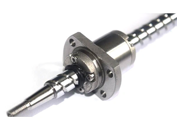
A ball screw model number does not completely describe the ends that connect it to a machine. Bearing seats, locking features and the motor coupling must work together with the chosen support arrangement. A clear drawing helps prevent a quotation from being based on different interface assumptions.
Send the complete screw envelope and detailed views of both ends, referenced to named datums. Identify the bearings, coupling and locking components that must fit. Mark unknown values for engineering review instead of filling them with guessed standard dimensions.
Start with the installed support arrangement
State which end is driven and how each end is supported. Include the bearing-block references and a sketch of their positions relative to the nut’s working travel. Mounting arrangement and span affect permissible compressive loading and rotational speed, so an end drawing should not be reviewed separately from the installed axis.[1]
Distinguish usable travel, threaded length and overall shaft length. Leave room for nut overrun limits, end supports, the coupling and installation access. A short shaft shown in a website model is not evidence of the length required by your machine.
Describe the interfaces that must fit
| Interface | Information to provide | Question to resolve |
|---|---|---|
| Support bearing | Bearing or support-unit reference, seat location, shoulder location and retention arrangement. | Which dimensions and fit requirements come from the selected bearing assembly? |
| Drive coupling | Coupling reference, bore interface, engagement length and surrounding clearance. | Can it be assembled and clamped without interference? |
| Locking feature | The intended nut, thread or retention component, with its drawing where available. | Are its mating details and access clear? |
| Machine mounting | Support locations, nut attachment and the datum relationship to the guide system. | How will the axis be aligned and inspected after assembly? |
Use datums and inspection requirements deliberately
Identify the surfaces or axes used to locate and inspect the part. State required fits, runout or other geometric controls only where the design requires them, with units and the applicable drawing convention. If those requirements have not been established, ask for a proposed interface drawing rather than approving an incomplete one.
Keep screw lead accuracy, assembled positioning accuracy and shaft-end geometric requirements distinct. Positioning also depends on clearance, stiffness, temperature and guide behavior. An accurately drawn bearing seat alone does not establish the accuracy of the finished machine.[2]
For a replacement, separate measurements from requirements
Provide the original drawing or part identification if available, plus clear photographs of both ends and the nut mounting. Label measurements taken from a used part as measured observations; wear, damage or incomplete access may make them unsuitable as manufacturing requirements. Do not infer a bearing fit or thread specification from a photograph.
Note which existing components must be retained and which may change. A supplier can then flag an interface conflict before the replacement is treated as a direct fit.
Send one controlled quotation package
- Screw family, candidate model, lead and nut orientation, where already known.
- Drawing number, revision, units and a clearly identified approved or review status.
- Both shaft ends, complete length relationships and the mating component references.
- Operating stroke, load direction, speed, duty cycle and environment.
- A short list of unresolved dimensions or interfaces requiring confirmation.
The PFU product page and miniature ball screw family can help identify a starting configuration. They do not replace an approved end-machining drawing or confirm that every requested interface can be supplied.
Technical references
References explain general principles and do not transfer another manufacturer’s specifications to a Series Motion product.
Discuss your application
Send the drawing and operating requirements listed above for a configuration review.