
Crossed Roller Guide Selection: Stroke, Cage Travel and Mounting
October 19, 2026 · 5 min read
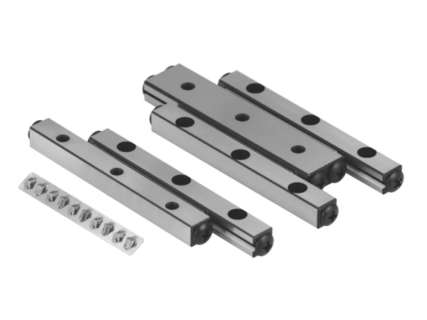
A short-stroke stage can fit inside a small envelope and still put demanding loads on its guide. Before selecting a crossed roller guide by rail length, check how the carriage, roller cage and surrounding parts move through the complete stroke.
Check travel and cage clearance first, then the directions and moments of the applied loads. Review mounting, alignment and service access with the chosen guide drawing. The rail length, one catalog rating or the word “precision” is not enough to confirm a complete stage.
Understand the finite-stroke arrangement
In a cage-type crossed roller guide, rollers are held between dedicated rails rather than recirculating through an unlimited-travel carriage. The cage moves as the table travels. THK’s illustrated cage arrangement has cage travel equal to half the table stroke; that relationship explains why both movements must be considered, but the allowable travel must come from the actual selected product drawing.[1]
Draw the carriage at both ends of the usable stroke. Check the cage position, supported overlap and clearance to nearby brackets, covers and cables. Include a defined approach to overtravel; do not treat a cage-retaining part as a machine stop unless the supplier explicitly permits that use.
Place the load, not just its weight, on the sketch
Mark the load center relative to the guide arrangement and include process forces, acceleration and external disturbances. An offset tool or camera can create a moment even when its mass is modest. This is a design example, not a claim about a tested customer installation.
Confirm what each published rating represents. A catalog may give values per rolling element or in a specified direction; those values cannot automatically be read as the capacity of the complete stage. The number of effective rolling elements and load direction matter in the manufacturer’s selection method. Static loading, shocks and fatigue-life calculations also require different checks.[2]
Review mounting before assuming smooth travel
Confirm the rail arrangement, locating surfaces, fasteners, adjustment access and the prescribed assembly sequence. Check the base and moving table as part of the structure; a guide cannot compensate for an unsuitable mounting surface or an imposed alignment error.
Discuss preload or clearance requirements with the supplier. More preload is not a general instruction for better performance. The required adjustment depends on the guide, load case and assembly procedure; this article does not provide a universal screw torque or preload setting.
Ask about cage behavior in the real duty
State whether the stage operates horizontally, vertically or on an incline, and describe its stroke pattern, reversals, vibration and environment. Ask what cage-position checks, retention provisions and travel limits apply to the chosen model. Do not assume a special anti-creep mechanism is included because another manufacturer’s guide offers one.
Review lubrication access and protection against contamination. Access should remain possible in the assembled machine, not just while the guide is on a workbench.
Prepare a stage review package
- Usable stroke and the permitted overall installation envelope.
- Load magnitude, direction, offsets and a sketch of the guide layout.
- Speed, acceleration, reversals, dwell and operating frequency.
- Orientation, environmental exposure and lubrication access.
- Required repeatability, positioning behavior and the proposed acceptance checks.
Use the Series Motion VR crossed roller guide page to start a model and drawing review. Confirm the rail/cage combination and its limits for the application. The page is one real product route, not a claim that a complete range of recirculating linear guides is available.
Before ordering, agree how full-stroke motion, cage position, assembly clearance and loaded behavior will be checked. These application checks are more useful than an unsupported promise that every compact stage will achieve the same accuracy or life.
Technical references
- THK — cage-type cross-roller structure and motion
- THK — directional ratings and effective rolling elements
References explain general principles and do not transfer another manufacturer’s specifications to a Series Motion product.
Discuss your application
Send the drawing and operating requirements listed above for a configuration review.