
Miniature Ball Screw Selection: Lead, Load and Linear Guide Matching
October 19, 2026 · 5 min read
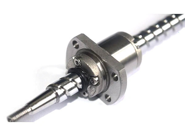
A compact positioning stage needs more than a screw that fits the available space. The lead must suit the motion profile, the screw must carry the axial demand, and the guide must support the carriage without forcing side loads into the nut.
Start with travel, speed and load direction. Shortlist a diameter-and-lead combination, check the screw and its supports, then size the guide from the payload position and moments. A smaller lead or a larger guide does not automatically make the whole axis more accurate.
1. Choose lead from the move, not the model name
Lead is travel per screw revolution. For a rotating screw, the required speed is n = 60v / l, where v is linear speed in mm/s, l is lead in mm/rev and n is rpm. As a hypothetical example, a 20 mm/s move requires 600 rpm with a 2 mm lead and 240 rpm with a 5 mm lead. These are kinematic calculations, not approved operating points.
A finer lead reduces travel per revolution but needs more revolutions for the same move. Check the available motor torque across the required speed range, acceleration and nut speed limit. Also check shaft critical speed for the actual unsupported span and bearing arrangement. Command resolution, positioning accuracy and repeatability are different requirements.[1]
2. Separate axial demand from guide loading
List the process force, acceleration force and guide resistance through the cycle; include gravity for an inclined or vertical axis. Check peak/static loading separately from the load spectrum used for fatigue-life estimation. The catalog dynamic rating is a reference for a life calculation, not a promised working load or service life.
Check compressive buckling at the relevant free length, support-bearing capacity and mounting stiffness. For vertical motion, specify what the machine must do after loss of power; do not assume a ball screw will hold the load by itself.[2]
3. Match the guide to the carriage
The screw produces axial drive; the guide supports the moving assembly and constrains its path. Review side loads and overturning moments from an offset payload, tooling or cable drag. Guide spacing, mounting surfaces and alignment matter as much as a catalog load figure. Do not use the nut to correct a misaligned carriage.
For a compact stage, the VR crossed roller guide is a separate product to review. Its available travel, rail/cage arrangement and mounting requirements must suit the application. Its presence in the catalog does not establish a verified pairing with a particular screw. Our earlier note on ball screws and guide rails gives additional context.
4. Check the assembled envelope
Use the miniature ball screw category to compare published options, then review the PFU flange-nut product for mounting details. Check flange clearance, fastener access, nut travel, bearing blocks, coupling and lubrication access. Usable stroke is not the same as overall screw length.
Explore a PFU flange-nut envelope
PFU0802 · rolled version · catalog page 3. This is a simplified exterior illustration, not production CAD. It omits raceways, tolerances, lubrication details and shaft-end machining. The short smooth shaft is a display reference, not an ordered shaft length.

Live 3D loads automatically as this viewer reaches the screen.
Drag with one finger to rotate; use two fingers to zoom. Scroll the page outside the viewer. Keyboard: focus the viewer and use arrow keys. No automatic rotation.
Send a useful selection request
- Usable stroke, available envelope and mounting orientation.
- Moving mass, process-force direction, offset distances and any shock loads.
- Speed, acceleration, reversals, dwell time and cycles per hour.
- Required positioning accuracy, repeatability and allowable lost motion.
- Existing guide layout, end supports, motor/drive and lubrication environment.
Include a sketch showing the screw centerline, guide locations and load center. This lets the screw, guide and support arrangement be reviewed together before a model is confirmed.
Technical references
References explain general engineering principles. They do not certify a Series Motion model or transfer another manufacturer’s ratings to it.
Discuss your application
Share the duty cycle and installation sketch, together with the requirements listed above, for a configuration review.
Related products
Grinded Miniature Ball Screw
Miniature ball screw is suitable for high speed, high precision, small load, frequent start/stop operation, such as Robot arm, Semiconductor Production Equipment, Medical Equipment, Precision Measuring Equipment, etc.
View product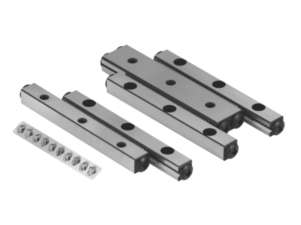
VR SERIES
Crossed roller guide is a high precision, high load, high rigidity linear motion track, usually used in robots, automation equipment, machining centers, precision measurement equipment and other equipment and systems that need to achieve high precision linear motion.
View product