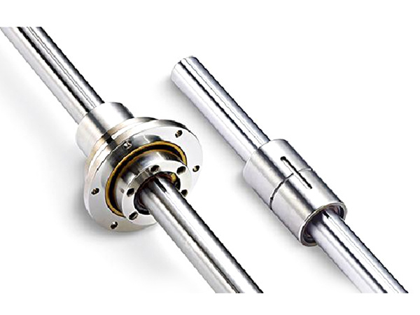
Ball Spline Rotary Support: Separate Nut Rotation from Axial Sliding
November 4, 2026 · 6 min read
A ball spline contact and a bearing that supports a rotating nut perform different functions. The spline couples torque between the shaft and nut while allowing relative axial movement. A rotary support allows the nut or its cartridge to turn relative to the machine frame. Define both interfaces when a machine requires linear and rotary motion on the same shaft.
This guide helps review a motion architecture and its scope of supply. An SL or SO nut designation identifies the spline component; it does not, by itself, specify a complete rotary bearing cartridge. Start with the SL or SO product reference and describe any additional support assembly separately.
Identify which components rotate relative to one another
Label the shaft, spline nut, nut carrier and stationary frame. For each pair, state which relative movement is required and which movement must be restrained. A shaft that rotates in the machine can still have very little relative angular movement within its spline nut because the two rotate together.
If the nut is rotationally fixed to the frame, the spline transmits the reaction that restrains shaft rotation while permitting axial sliding. If the nut rotates in a supported cartridge, it can transmit drive torque to the shaft while the shaft moves axially relative to it. The support between cartridge and frame provides a different rotational interface from the spline contact.
Keep the axial drive explicit. Nut rotation does not impose a screw lead on a conventional straight-raceway spline. The screw and spline function guide covers that distinction; the question here is how the required motion is supported and connected.
Assign a function to every interface
| Interface | Function to define | Drawing information |
|---|---|---|
| Shaft to spline nut | Torque transfer and permitted axial sliding. | Matched components, working range and specified contact condition. |
| Nut to rotating carrier | Attach the nut to the part that rotates with it. | Torque connection, axial location and retention. |
| Rotating carrier to frame | Support rotation and the loads assigned to that bearing arrangement. | Bearing configuration, seats, retention and reference axis. |
| Rotary drive to carrier | Introduce drive torque without assuming the spline is the drive connection. | Actual coupling, pulley or other specified interface and applied loads. |
| Axial drive to moving member | Generate the required translation independently of the spline’s sliding freedom. | Connection, motion range and how that connection accommodates rotation. |
Purpose-designed rotary spline units can integrate support bearings with the spline nut. A separately designed carrier uses its own support arrangement. In either case, obtain the complete assembly drawing and component definitions. The presence of a flange or cylindrical nut body alone is not evidence of an integrated rotary support.
Trace external loads to the frame
Mark where payload forces, process forces and drive forces enter. Trace their route through the shaft, spline contact, carrier, support bearings and machine structure as applicable. A force carried by one interface is not automatically carried in the same direction or magnitude by every other interface.
For example, a belt driving a carrier can apply a transverse load at the pulley location in addition to the transmitted torque. That force and its offset belong in the rotary support review. Do not assess the support bearing only from the spline’s torque requirement.
Specify which bearing arrangement locates the rotating assembly axially and which parts carry any external axial force. The spline’s ability to slide does not define the axial locating function of the cartridge. Use the documented bearing arrangement and load calculation for the proposed construction; a spline contact rating does not rate the complete cartridge.
Check alignment and service interfaces together
Define the common axis of the support bearing seats, nut mounting interface and shaft path. Misalignment can make a nominally free sliding motion resist movement. Review the assembled geometry rather than checking each housing diameter independently.
Also identify access to each lubrication point. The spline contact and the rotary support may have separate service requirements or delivery paths. Confirm the approved method for each; do not assume a fitting on the cartridge lubricates both. The lubrication layout guide provides the related access review.
State the assembly boundary before ordering
Identify who supplies the spline pair, carrier, support bearings, retention hardware, drive interface and housing. Record which parts are supplied assembled and which interfaces the machine builder must complete. Request confirmation of the proposed construction rather than inferring an available integrated unit from another manufacturer’s design.
Download the rotary support interface worksheet (CSV). Attach the labelled motion and load-path sketch, required travel and rotation, and the mating-part drawings. Keep any unresolved support or service responsibility visible in the inquiry.