
Ball Nut Mounting Drawing Checklist: Flanged, Cylindrical and Threaded Interfaces
October 20, 2026 · 3 min read
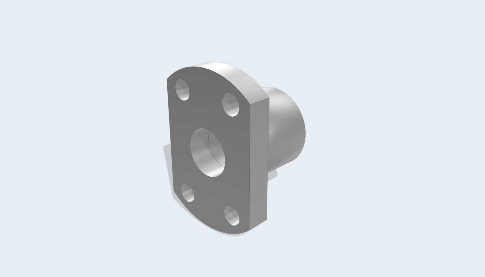
Illustrative exterior from the drawing reference viewer; not manufacturing CAD.
Use this checklist to review the interface between a ball nut and its housing. Record the information needed to discuss the mounting arrangement with your supplier.
The examples below come from individual source drawings. They describe the external features shown on those drawings; the dimensions do not apply to every model in a family. Bearing seats, couplings and screw shaft ends belong in a separate shaft-end drawing review.
Identify the mounting features on the selected drawing
Start with the processed landscape PDF for the selected reference. Record its full title and source identifier with your notes. The following examples show the kinds of information to collect.
| Drawing example | Features to check in its source | Information needed from the housing drawing |
|---|---|---|
| F0802A | Four-hole flange, body envelope, flange thickness and dimension across the flats | The matching attachment layout and the surfaces intended to locate the nut |
| C0802A | Cylindrical body diameter, stated deviations and overall length | The proposed housing interface and the intended method of locating and retaining the nut |
| T0802A | External mounting-thread designation and dimensioned threaded segment | The specified mating thread and the available assembly space |
| S0601A-13x13x11 | Overall block dimensions, mounting thread pattern and face groove dimensions | The matching hole layout and the intended locating faces |
| SFA1605-3.8 | Six-hole flange, front projection and body envelope | The corresponding locating feature, attachment layout and surrounding space |
These observations are supported by the five source drawings listed below. The table does not prescribe a housing fit, a tightening torque or a retention design. Specify these requirements for the actual assembly; do not infer them from a website image.
Prepare the nut-mounting review sheet
Record the selected drawing reference, its units and any available revision information. If the supplied file does not identify a revision or approval status, leave that as an open question instead of assigning one.
Copy each relevant dimension with its label. Keep body size, overall length, hole position, thread designation and locating features separate. Include the stated deviations or tolerance notation where the drawing provides them. Do not assign a diameter to an unmarked opening based on the model name or a similar part.
Attach the mating housing drawing or an installation sketch. Indicate which surfaces, holes or threads are intended to connect, and list any existing components that must be retained. If the interface is not yet designed, describe the available envelope and ask for it to be reviewed; the nut reference alone does not specify the matching housing.
List unresolved items explicitly. Examples include a missing dimension, an unidentified drawing revision or a mating feature with undefined requirements. Clearly label measurements taken from an existing part and distinguish them from the requirements for the new part.
Keep the drawing reference with the inquiry
In the 3D Selection directory, choose a nut family and then a drawing reference. The inquiry link includes the selected reference. Check that reference against the processed landscape PDF before sending the request, and include the housing information and open questions collected above.
The interactive model is a communication aid. It uses nominal external dimensions and shows unmarked openings for illustration only. It does not provide internal raceway design, return-passage geometry or manufacturing CAD. A source record does not establish compatibility with another nut, screw or housing.
Source records do not imply compatibility or interchangeability. Confirm the complete interface against an approved drawing before making a final installation or manufacturing decision.
Source drawings
Each link opens page 1 of a processed landscape drawing copy. These files support the feature descriptions above; their availability does not establish approval for your application.
- F0802A — processed landscape drawing
- C0802A — processed landscape drawing
- T0802A — processed landscape drawing
- S0601A-13x13x11 — processed landscape drawing
- SFA1605-3.8 — processed landscape drawing
Public downloads are processed landscape reference copies. Only the company-brand cell is replaced with “Custom Manufacturing / to Your Drawings”; drawing dimensions, tolerances, model titles and technical fields are retained. Supplied originals are stored in a private backup. Source identifiers are the first 12 characters of the supplied original PDF SHA256, not a model number, revision or approval status.