
Ball Screw Buckling: Check Compression, Span and Nut Position
November 4, 2026 · 6 min read
A ball screw can meet a nut load-rating requirement and still need a larger shaft or a different support layout to carry compression. Review shaft buckling at the relevant nut positions before treating a catalog load rating as the capacity of the installed axis.
First identify which shaft segment is compressed
Draw the nut, the shaft supports and the direction of the external axial force. Show where thrust enters the screw and where the bearing arrangement transfers it into the machine. Repeat this sketch for the relevant process, acceleration and deceleration conditions.
A reversal of travel does not by itself tell you whether the shaft is in tension or compression. The applied force and its reaction determine that. On a moving-nut axis, the length of the loaded segment can also change as the nut travels. Identify the positions that combine significant compression with an unfavorable span, rather than checking only the home position.
For the complete force history, start with our ball screw overload checklist. This page focuses on the shaft geometry and the information needed for the buckling calculation.
Define the calculation span and restraint together
Use the mounting diagram and length definition required by the selected engineering method. The relevant distance for buckling is not automatically the overall shaft length, working stroke or bearing-to-bearing distance used in a critical-speed check. A nut location may form part of the calculation model; confirm the assumed restraint rather than treating the nut as a universal ideal support.
| Input | Evidence to provide | Common mistake to avoid |
|---|---|---|
| Root or thread minor diameter | Current shaft drawing or confirmed model data | Using nominal diameter or ball diameter instead |
| Relevant loaded span | Dimensioned layout at each governing nut position | Entering stroke or overall length by default |
| End restraint | Bearing arrangement, retention and mounting details | Assigning a fixed condition from a support-block label alone |
| Maximum compression | Force direction and magnitude for each load case | Using only the average force from a life calculation |
| Calculation convention | Formula, units, applicability and included margin | Combining a coefficient from one method with another method’s span |
On the published miniature screw tables, d denotes the screw diameter and Da denotes ball diameter. Neither field should be substituted for a confirmed thread minor diameter. Ask for the missing shaft data when it is absent from the reference table.
Use geometry ratios to understand a proposed change
For an ideal elastic column model with the same material and end-restraint assumptions, the buckling threshold varies with dr4 / L2, where dr is the root diameter and L is the span defined by that model. This relationship is useful for comparing alternatives; it does not produce an approved operating force by itself.
| Change from the reference geometry | Threshold ratio | What it illustrates |
|---|---|---|
| Span increases from 600 to 900 mm; root diameter unchanged | (600 / 900)2 ≈ 0.444 | About 44% of the original ideal threshold |
| Root diameter increases from 10 to 12 mm; span unchanged | (12 / 10)4 ≈ 2.074 | About 2.07 times the original ideal threshold |
| Both changes occur together | 2.0736 × 0.4444… = 0.9216 | The combined ideal threshold remains below the reference |
The dimensions above are assumed for arithmetic. They do not identify a Series Motion model, establish a root diameter for a nominal size or certify a load. If the support design changes, this comparison no longer holds with an unchanged restraint factor.
Keep the other load limits in the review
Check the shaft’s permissible tensile/compressive stress, nut static loading, rolling-fatigue life, bearings, end features and attachments separately. Also review speed and stiffness. Passing a buckling check leaves those requirements to be resolved. Use the chosen supplier’s complete method and its stated margins; establish whether a published result already includes a reduction before applying another factor.
Send a position-based review sheet
For each relevant nut position, record the axial force, force direction, compressed segment, calculation span and restraint assumptions. Attach the screw drawing with the confirmed root diameter, the bearing references and the operating cycle. Mark provisional inputs so they can be checked before a model is confirmed.
Compare the published ground miniature ball screw and rolled miniature ball screw options after defining these conditions. Their catalog listings do not confirm a permissible compression load for your layout.
Request a compression-load review with your drawing and the position-based load cases.
Related reading
Related products
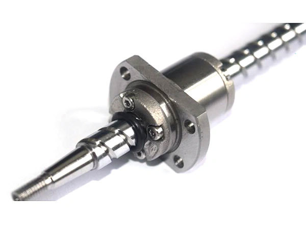
Ground Miniature Ball Screw
Ground miniature ball screws use ground raceways. Review the published model tables for diameter, lead, nut geometry and load ratings, then confirm accuracy and preload for the complete assembly.
View product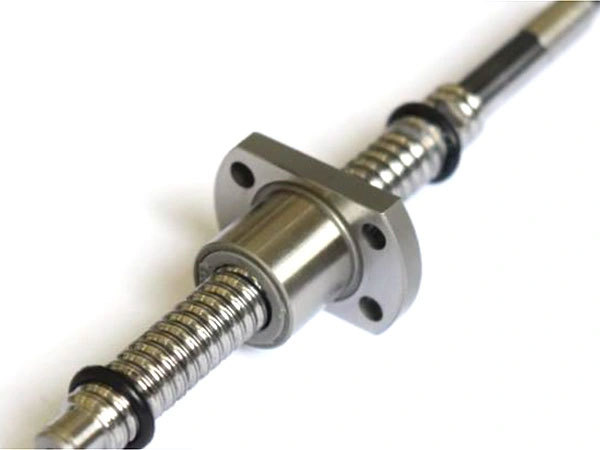
Rolled Miniature Ball Screw
Rolled miniature ball screws use rolled raceways. Compare the published diameter, lead, nut dimensions and load ratings, and specify the required travel accuracy, preload and operating conditions.
View product