Ball Spline vs Round-Shaft Linear Bushing: Decide the Torque Path
November 4, 2026 · 6 min read
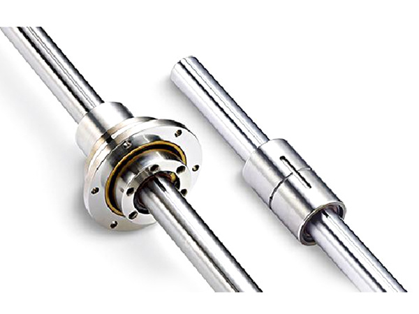
A ball spline and a conventional round-shaft linear bushing both guide straight travel, but they do not provide the same torque path. A ball spline uses longitudinal raceways to couple the nut and shaft in rotation while permitting axial sliding. A conventional bushing running on a cylindrical shaft needs a separate arrangement when the machine must prevent relative rotation.
Choose between guidance arrangements from the required motion and load path, rather than from the outside appearance of the nut. This comparison concerns conventional round-shaft linear bushings; special grooved or anti-rotation guide products need their own specifications.
Decide where the rotational reaction belongs
Mark the payload, shaft, guide housing and frame on a motion sketch. State which part must move axially, which part may rotate and where an applied torque must be reacted. If the same shaft must slide and transmit torque through its guiding nut, that is a spline function to review.
If the machine instead uses a separate guide or rotation-stop mechanism, identify the forces that mechanism carries. Two spaced guides can resist a carriage moment through a force couple. That arrangement does not make each conventional round-shaft bushing a torque-transmitting spline about its own shaft axis.
Do not treat the absence of a positive rotational connection as permission to spin a shaft continuously inside a linear bushing. The permitted motion must follow the selected product’s specification. A rotary bearing function and a straight-travel guide function are separate requirements.
Compare the complete guidance arrangement
| Requirement | Ball spline arrangement | Conventional round-shaft bushing arrangement |
|---|---|---|
| Axial motion | Nut and matching grooved shaft permit relative sliding. | Bushing guides travel on a specified cylindrical shaft. |
| Torque or rotation restraint | Review the spline contact and its connection to the machine. | Define a separate guide or restraint when required. |
| Shaft interface | Raceway configuration and contact condition belong to the matched design. | Use the shaft requirements specified for the selected bushing. |
| Moment support | Review nut arrangement, reactions and applicable ratings. | Review the complete guide spacing, bearing arrangement and reactions. |
| Installed result | Include shaft, nut, mounting and any rotary support. | Include bushings, shafts, housings and any separate rotation restraint. |
Both arrangements still need a drive if controlled axial travel is required. Neither product name specifies a screw lead or a complete actuator. The existing screw and spline function guide explains the drive-versus-guidance distinction.
Keep ratings with the exact product and load case
Raceway contact geometry differs between a spline and a conventional bushing on a cylindrical shaft. The load capability must therefore be checked using the selected product’s ratings and calculation method. Equal shaft diameter does not establish equal capacity, stiffness, life or allowable moment.
Compare candidates under the same payload position, process forces, travel and operating cycle. Include any additional guide or restraint in the system calculation. A component-level advantage cannot establish the result for two differently arranged machines.
Keep the rating units and life basis explicit, and identify the required clearance or contact condition. Do not use a general performance ratio between product categories as a sizing rule. The combined-load review guide covers the spline calculation evidence.
Check space and interfaces beyond the shaft diameter
A spline arrangement may place sliding and torque guidance on one shaft. An alternative with separate rotation restraint occupies its own space and needs alignment, mounting and service access. Compare those complete envelopes rather than only the two bearing outside diameters.
For an existing machine, record which parts must remain: shaft, housing bore, flange pattern, support locations or tooling attachment. A similar nut envelope does not show that a grooved shaft and a cylindrical shaft are interchangeable, or that the retained assembly can perform a new function.
Use the replacement compatibility guide when a proposed change retains any old components. For a rotating spline nut, define the separate support described in the rotary support guide.
Send a functional comparison rather than a category ranking
Prepare one requirement sheet for each complete candidate. Show the axial motion, torque reaction, moment support, required working-point behaviour, environment and service access. Identify which drawing and component specification supports each requirement.
Download the guidance-arrangement comparison sheet (CSV). For a spline proposal, start with the published SL or SO reference and submit the machine requirements for confirmation. A general comparison does not establish availability of a particular alternative product or assembly.