
Ball Screw Usable Travel: Working Stroke and Overrun Clearance
November 4, 2026 · 6 min read
Ball screw working stroke must fit inside the permitted nut travel, with room for the machine to stop. A threaded length or overall shaft length alone does not define usable travel. Establish the nut’s allowed positions from the assembly drawing, then place the working endpoints and protection features within those limits.
Mark three different boundaries
Choose a nut or carriage datum and dimension its position from a fixed machine datum. Use that same reference for the working endpoints, limit settings and collision checks. Include the complete nut envelope, attachments, lubrication fittings, covers and nearby supports when reviewing interference.
| Boundary | What to establish | Evidence needed |
|---|---|---|
| Permitted nut positions | The range in which the selected nut may operate while remaining correctly engaged and clear of interference | Confirmed screw/nut drawing and application review |
| Normal working endpoints | The positions required to perform the process, including normal approach and positioning behavior | Motion sequence and coordinate definition |
| Limit and stopping positions | Where a protective response begins and where motion ends under the defined stop condition | Control behavior, response time and stopping verification |
Thread runouts, end machining and the nut’s internal engagement requirements must be considered when establishing its permitted positions. Do not obtain that range simply by subtracting a catalog nut length from the overall screw length. The shaft-end drawing checklist explains the separate end interfaces.
Allocate the working travel before choosing shaft length
Consider a hypothetical drawing that has already established permitted positions for the chosen nut datum from 0 to 300 mm. If the normal working endpoints are 20 and 270 mm, the working stroke is 270 − 20 = 250 mm. The remaining distances to the permitted-position boundaries are 20 mm at one end and 30 mm at the other.
Those remaining distances are an allocation to be reviewed, not an approved stopping margin. Locate limit actuation and the resulting stop positions inside the permitted range, allowing for the actual direction of approach, tolerances and control behavior. Review both ends independently; gravity, speed or a different process load can change the stopping requirement.
The 300 mm range in this example is an assumed permitted datum-position range. It is neither a threaded length nor a proposed shaft length. No catalog model or supply capability is implied.
Account for travel after a stop is requested
A limit signal does not stop a moving carriage instantly. For a simple preliminary estimate with constant approach speed during the response delay, followed by constant deceleration to rest:
s = v × tr + v2 / (2a)
Use v in mm/s, response delay tr in seconds and deceleration magnitude a in mm/s² to obtain distance s in mm. For assumed values of 100 mm/s, 0.05 s and 500 mm/s², the delay travel is 5 mm and the deceleration travel is 10 mm, giving a simplified total of 15 mm.
This arithmetic is not a validated machine stopping distance or a limit-setting recommendation. It assumes the stated speed is maintained through the delay and the stated deceleration is achieved afterward. Jerk-limited profiles, continued acceleration, load direction, drive limits, detection variation and position uncertainty can change the result. Use the actual stop behavior and verify the complete stopping envelope under the specified operating conditions. Loss of power may produce a different response from a controlled stop.
Keep nut collision outside the stopping strategy
Do not use the ball nut striking a support, shoulder or mechanical stop as the normal method of ending travel. Impact can damage the nut. Any separate mechanical stopping feature must be designed for its intended load path and condition while keeping the nut within its permitted travel. Clearance in a static drawing alone does not establish impact capacity.
If a nut overruns and rolling elements are lost, stop using the assembly and follow the machine procedure for securing the load. Record the event and request model-specific inspection. Our ball-loss service checklist covers the information to retain.
Prepare one travel drawing for the review
- Identify the screw and nut, drawing revision, coordinate datum and travel direction.
- Show permitted nut-datum positions, working endpoints, limit-actuation locations and stopping envelopes at both ends.
- Include nut attachments, supports, covers, lubrication access and other interference limits.
- Record approach speed, load orientation, relevant stop modes and how stopping behavior will be verified.
- Keep working stroke, effective threaded region, bearing span and overall shaft length separately dimensioned.
Review the miniature ball screw family with this layout. A listed model does not establish the shaft length, end machining, limit sensors, brake or stop hardware included in a proposed assembly.
Send the travel layout for review, identifying dimensions and stopping assumptions that still need confirmation.
Related reading
Related products
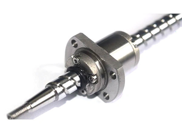
Ground Miniature Ball Screw
Ground miniature ball screws use ground raceways. Review the published model tables for diameter, lead, nut geometry and load ratings, then confirm accuracy and preload for the complete assembly.
View product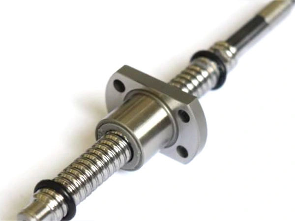
Rolled Miniature Ball Screw
Rolled miniature ball screws use rolled raceways. Compare the published diameter, lead, nut dimensions and load ratings, and specify the required travel accuracy, preload and operating conditions.
View product